A1110-40-QE-100V
4-quadrant
voltage and current amplifier
DC-1 MHz | 70
V/�gs | 1200 W (source) | 600 W (sink)
l Fully configurable and operable by means of the
supplied software
l Symmetrical input
l Series / parallel connection in case of higher
voltage / current requirements
l USB port as series (LAN interface optional)
l Automatic switching of 3 supply voltages
l Monitor output voltage / current
l 6 configurable compensation networks for
inductive loads
in the current amplifier operating mode
l sense output
|
Output
voltage |
�� 100 Vpeak ] |
|
Output
current |
�� 40 Apeak |
|
Performance range |
DC �V 200 kHz |
|
Frequency
response |
DC - 1 MHz
(Small signal -3 dB) |
|
Slew rate |
70 V/�gs |
|
Voltage
amplification |
10 �� 0.1 % (��
0.01 % /�XC) |
|
Offset |
�� 1 mV (�� 0.1 mV /�XC) |
HUBER
Power
Amplifiers
and Driving
Pulsed Currents
1 Introduction
ISO 11452-8 is a widely used automotive standard for immunity testing against magnetic fields.
In the frequency range from 15 Hz to 150 kHz, a sinusoidal
current is applied to a coil with a power
amplifier.
Recently, however, magnetic field tests with pulsed waveforms up to e.g. 500
Hz
and 30 Ap have
been
required. This task can be solved conveniently and reliably
with a HUBERT A1110-40-QE-100V power amplifier in current amplifier mode.
The General Motors Standard GMW3097:2019 for
electronic/electrical components defines fast pulse-shaped signal forms for
testing immunity to magnetic fields. See how you can comfortably perform this
requirement with the A1110-40-QE-100V in current amplifier mode
2 Current Mode
Figure 1 shows the time course of the current (blue) of an A1110-40-QE-100V in current mode with
optimized compensation network for an inductive load.
The maximum output voltage (red) of the power amplifier is required for a short period of time for the rapid
increase of the load current. This maximum voltage then drops to a small value in the steady state of the current, depending on the resistive component of the inductance. In this example from approx. 100 V to Uout_min = 32 A * 80
mR = 2.56 V.
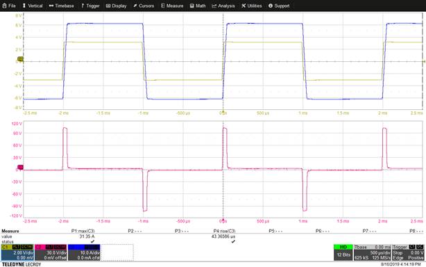
Figure 1: C1:Uin, pulse 6,2 Vpp/500 Hz; C2:Umon; C3:Imon; current mode; Load= 80
mR+90 uH
During this time of steady state (here approx. 1 ms), a high power dissipation occurs in the power amplifier due to the difference between high operating voltage and low output voltage. The
amplifier must be dimensioned accordingly for a safe and longer operating time.
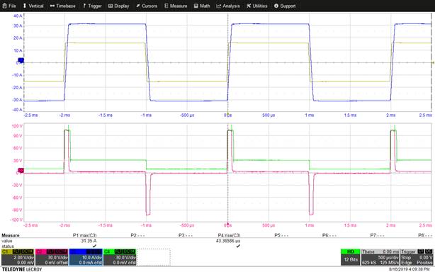
Figure 2: C1:Uin, pulse, 6,2
Vpp/500 Hz; C2:Umon; C3:Imon;
C4:+Ub, current mode
With the A1110-40-QE-100V power amplifier, this problem is minimized because the operating voltage is automatically
adapted to the required output voltage.
Figure 2 illustrates the connections: During the period in which a high output
voltage is required,
the operating voltage (green, only the positive operating voltage +Ub is shown) is switched to the highest level. In the further course of time, +Ub is lowered to a minimum value.
This technology reduces the losses in the A1110-40-QE-100V during operation at reactive loads to
a minimum and thus achieves a significantly higher degree of efficiency compared to power amplifiers with a fixed, static operating voltage.
For comparison, Figure 3 shows the current transfer curve of the A1110-40-QE-100V in
voltage
F gu e 3 C1 U
n 1 2 Vpp/500 Hz C2 Umon C3 mon
vo age
mode
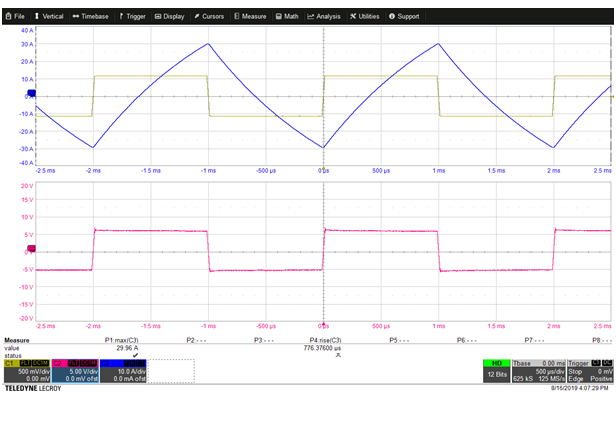 mode. As expected, this does not meet the requirement for pulse current.
Figure 3: C1:Uin,
1,2 Vpp/500Hz; C2:Umon; C3:Imon; voltage mode