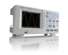
Digital oscilloscope DS-5100B series

DS-5100B

Digital oscilloscope DS-5100B series            Functions

Equipped with digital filter

Screen example

Screen example

Screen example

Noise-laden signal with high frequency components


Use low pass filter with DS-5100B series digital filter for left signal

The noise is removed and the signal appears clearly

Low pass filter
(LPF)

Set the upper limit frequency and cut high frequency components.
The DS-5100B series has a 20MHz band limitation function even in hardware, but if you use the LPF function, you can clearly display a signal buried in noise.


High pass filter
(HPF)

Set the lower limit frequency to cut low frequency components.
Since the signal component that is swinging in synchronization with the power supply frequency can be removed, high-speed signals can be stably observed.

Band Pass Filter
(BPF)

Extract any frequency range.
It is effective for extracting the signal you want to observe from the waveform that contains many frequency components.

Band Rejector Filter
(BRF)

Cut a specific frequency range.
For example, you can remove the signal by focusing on the frequency components of the noise.

Zoom function with excellent operability

Knob

Screen example

One push of the time axis knob!

Automatic measurement of waveform parameters

Vpp

Peak-to-peak voltage

Vmax

Maximum amplitude

Vmin

Minimum amplitude

Vamp

Waveform voltage between Vtop and Vbase

Vtop

Voltage between GND and flat top of waveform

Vbase

Voltage between GND and bottom flat part of waveform

Vover

Overshoot

Vpre

Pre-shoot

Vavg

Arithmetic mean of all displayed data

Vrms

Effective value of voltage

Rise

Rise time

Fall

Fall time

+Wid

Pulse width (positive pulse)

-Wid

Pulse width (negative pulse)

Delay1 → 2

Delay time between rising edges of CH1 and CH2

Delay1 → 2

Delay time between the falling edges of CH1 and CH2

+Duty

Duty ratio

-Duty

Duty ratio

Screen example

FFT analysis The
DS-5100B series can display the observed signal in the frequency domain like a spectrum analyzer by performing FFT calculation.
Another advantage of the FFT calculation method over other frequency conversion methods is that it can calculate even single-shot signals and slow-repeat signals. The DS-5100B series can also perform burst waveform analysis, repetitive waveform frequency analysis, and amplitude analysis.

Screen example

Screen example

FFT calculation result using rectangular window

FFT calculation result using Hamming window

Average mode (averaging)

The DS-5100B Series has an average mode that reduces uncorrelated random noise by repeatedly capturing and averaging waveforms.

Screen example

Random noise can be reduced by averaging.

Pass/Fail function

Screen example

It monitors the input signal for changes and outputs Pass and Fail signals depending on whether the signal meets a predefined mask.

Waveform recorder function

The DS-5100B Series can automatically record abnormal signals by combining the measured waveform with recording at a fixed time interval of up to 1,000 frames and the Pass/Fail function.
You can rely on the oscilloscope to monitor the waveform for a long time.

English display and Japanese display switching function

Equipped with help function

Screen example

Screen example

Persist display

With the DS-5100B Series, you can observe image fluctuations such as jitters on the screen afterimage.

Screen example

Digital oscilloscope DS-5100B seriesPeak detection mode

Equipped with Peak Detect mode

The DS-5100B series has a peak detection mode. In this mode, the maximum and minimum values ​​of the signal are acquired, and only the maximum and minimum points are detected from many acquisition points.
You can also avoid aliasing in this mode.

■ Strong against noise detection

It is a waveform that supplements a 50Hz commercial power supply with thin pulses mixed in normal mode.

Screen example

Normal Mode Normal Mode

In peak detection mode, even if the sampling speed is slowed by setting the time base to a slow range, the maximum sampling is always supplemented, and the maximum and minimum values ​​are recorded and displayed. With this mode, you won't miss the small pulses that are introduced into the slow signal.

Screen example

Peak Detect Mode Peak Detect Mode

■ Strong against aliasing

This is a waveform that supplements a 15 MHz sine wave in normal mode 1 GS/s.

Screen example

If a 15MHz signal is sampled at a slow cycle such as 5MS/s or less than 1/2 of that of the signal, it may be converted to a frequency different from the original and observed. This is called aliasing.

Screen example

The peak detection mode of the DS-5100B Series is a function that compensates for insufficient sampling speed, and holds and displays the peak value between sampling points.
 If you use the peak detection function, aliasing is less likely to occur and you can intuitively recognize that sampling is slow for the input signal.

Screen example

Digital oscilloscope DS-5100B series             Specification


DS-5110B

New
DS-5107B

New
DS-5105B

Vertical axis

frequency band

100MHz

70MHz

50 MHz

Band limitation

20MHz

Number of input channels

2ch

Vertical sensitivity

2mV/div ~ 10V/div

DC gain accuracy

+/- 3% (10mV/div to 10V/div)
+/- 4% (2mV/div to 9.9mV/div)

Offset range

±2V (2mV/div to 245mV/div), ±40V (250mV/div to 10V/div)

Maximum input voltage

400V (DC+AC peak) CAT

Input coupling

AC, DC, GND

Input impedance

1MΩ // About 15pF (DC coupling)

Vertical resolution

8 Bit

Inversion

○ (Software inversion)

Probe sensitivity switching

1X, 10X, 100X, 1000X (manual)

Data capture

Capture mode

Normal, average [2 to 256 times (power of 2)], peak detection

Peak detection pulse width

10 ns

15ns

20 ns

Maximum sampling rate

Number of channels

Normal mode

Long mode

1ch

1 GS/s

500 MS/s

2 ch

500 MS/s

250MS/s

XY mode: 100MS/s, roll mode: 512kS/s

Highest equivalent sampling

10GS/s

5GS/s

Time base stability

50ppm or less

Maximum memory length

Number of channels

Normal memory

At the time of long memory

1ch

16k points

1024k points

2 ch

8k points

512k points

Horizontal axis

Display mode

YT, XY, roll mode

Time base range

5ns/div ~ 50s/div

10ns/div ~ 50s/div

Roll mode range

50ms/div ~ 50s/div

Trigger

Trigger source

CH1, CH2, AC LINE, Ext

Trigger mode

Auto, normal, single

Hold off

100ns ~ 1.5s

Trigger type

Edge, pulse, video

Trigger level range

Internal trigger: ±6 div, External trigger: ±1.2V

External trigger maximum input voltage

400V (DC+AC peak) CAT

Find level

Optimal setting of trigger level (at signals above 50Hz)

Forced (manual) trigger

Measurement

Cursor measurement

Voltage measurement (ΔV), time measurement (ΔT), frequency measurement (1/ΔT)

Automatic measurement
*1

Vpp, Vamp, Vmax, Vmin, Vtop, Vbase, Vavg, Vrms, overshoot, preshoot, frequency, period, rising, falling, +pulse width, -pulse width, +duty, -duty, delay 1->2 ↓, delay 1->2↑

Frequency counter

6 digits

Calculation

function

Addition, subtraction, multiplication, FFT

Screen display

Size, resolution

5.7 type (320 x 234 pixels)

LCD

Color TFT

Persistence
(overlaid display)

Infinite time

Probe calibration signal

Output voltage

3V +/-5% (with a load of 1 or more)

Output frequency

1kHz +/- 0.1%

Waveform processing

Zoom function

Simultaneous display of enlarged horizontal axis waveform along with original waveform

Digital filter

Low pass, high pass, band pass, band reject

REF function

Can be displayed as a reference waveform

Admission decision

Pass/fail judgment by mask

Waveform recording

Record, play, save

General

Menu/help language

English, Japanese

Auto setup

Optimal settings for vertical axis, horizontal axis, and trigger (with undo function)

Measurement condition, data save/read function

Built-in memory: 10 waveforms, 10 panel settings
USB memory: Bitmap, CSV, waveform, panel settings
* Math waveforms cannot be saved as CSV and waveform data.

interface

USB (host, device), RS-232, pass/fail judgment output (BNC)

Power supply

AC power supply

AC 100V ~ 120V 50Hz/60Hz/400Hz, AC 200V ~ 240V 50Hz/60Hz

power consumption

40VAmax

Environmental characteristics

Operating temperature and humidity

0 ~ +40 / 80%RH or less

Performance guarantee temperature

+10 ~ +35

storage temperature

-20 ~ +60

mechanism

External dimensions

303mm(W) x 146mm(H) x 112mm(D) (excluding protrusions and accessories)

mass

About 2.2 kg (excluding accessories)

Accessories (number in parentheses)

probe

SS-0122 (10:1/1:1 switching) (2)

Other

Power cord (1), instruction manual (1)

*USB remote uses IWATSU Scope Viewer software.

However, only 32-bit OS is supported.

*1 Automatic measurement is calculated by compressing the sampling data and using about 600 points displayed on the screen.

option

Carrying bag DS-573A

Carrying bag pictures

Carrying bag photo (when opened)

DS-573A

When the bag is opened


Products list | brand | Model No. | Home