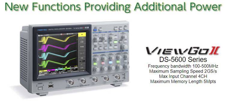
Digital Oscilloscopes DS-5600 SeriesSpecifications
![]()
DS-5654 |
DS-5652 |
DS-5634 |
DS-5632 |
DS-5624 |
DS-5622 |
DS-5614 |
DS-5612 |
||
Frequency bandwidth(-3dB) |
500MHz |
350MHz |
200MHz |
100MHz |
|||||
Rise time(Typical)) |
750ps |
1ns |
1.75ns |
3.5ns |
|||||
Input Channel |
4 |
2 |
4 |
2 |
4 |
2 |
4 |
2 |
|
Maximum Sampling Speed |
2GS/s (when 2 channels interleaved), 1GS/s (when all channels are in use) |
||||||||
Equivalent Sampling Rate |
100GS/s |
||||||||
Peak detect resolution |
1ns |
||||||||
Averaging |
2 to 65536 times (exponent of 2 step) |
||||||||
Maximum Memory Length |
5M points (when 2 channels interleaved), 2.5M points (when all channels are in use) |
||||||||
Vertical Resolution |
8-bit (When high-resolution calculation is valid: Maximum 12-bits) |
||||||||
Input voltage range |
2mV/div - 10V/div(1MΩ), 2mV/div - 2V/div(50MΩ) |
2mV/div - 10V/div(1MΩ) |
|||||||
Offset voltage |
2mV/div -
50mV/div : ±1V |
||||||||
DC gain accuracy |
±1.5% + (0.5% of fullscale) |
||||||||
Maximum Input Voltage |
±400Vpeak CAT I (1MΩ), 5Vrms (50Ω) |
±400Vpeak CAT I (1MΩ) |
|||||||
Band-limiting filter |
Analog form : 100MHz,20MHz,2MHz,200kHz |
Analog form : 20MHz,2MHz,200kHz |
|||||||
Digital Form: Select either LPF, HPF or SMA, 4 independent channels |
|||||||||
Input coupling |
GND, DC 1MΩ, AC 1MΩ,DC50Ω |
GND, DC 1MΩ, AC 1MΩ |
|||||||
Input Impedance |
1MΩ±1% //16pF、 50Ω±1% |
1MΩ±1% //20pF |
|||||||
Probe sense |
Automatic: 1:1、10:1、100:1、1000:1 |
||||||||
Timebase |
500ps/div ∼ 50s/div |
1ns/div ∼ 50s/div |
2ns/div ∼ 50s/div |
5ns/div ∼ 50s/div |
|||||
Standard probe |
SS-101R (multi-channel supplied as standard) |
SS-0130R (multi-channel supplied as standard) |
|||||||
Roll mode |
50ms/div ∼ 50s/div (100kS/s max) |
||||||||
Timebase (Clock) accuracy |
±10 ppm |
||||||||
Trigger function |
|||||||||
Trigger type |
Edge, Edge
ALT, Edge OR, Pulse Count, Pulse Width, Cycle, Dropout, TV, |
||||||||
TV mode / |
NTSC, PAL, Custom / Up to 3,000 / 1, 2, 4, 8 |
||||||||
Pulse Count Trigger |
1 to 9999 events |
||||||||
Pulse Width Trigger |
15ns to 50s |
||||||||
Period Trigger |
40ns to 50s |
||||||||
Dropout Trigger |
50ns to 50s |
||||||||
Pattern Trigger |
OR、NOR、AND、NAND |
||||||||
Trigger source / |
All Channels / HIGH, LOW, Don't Care / All Channel Independent Setting |
||||||||
Serial Trigger |
|||||||||
UART |
Trigger Selection |
START, STOP, Parity Error, Data Pattern |
|||||||
Bit Rate |
1,000bps to 1Mbps (set in units of 100bps) |
||||||||
Comparative Data Length |
5 to 8 bits |
||||||||
Signal Source |
CH1 to CH4, EXT (CH1, CH2, EXT for 2 channel function) |
||||||||
SPI |
Trigger Selection |
Data Pattern |
|||||||
CS Selection |
Idling time specified when no positive logic/negative logic or CS |
||||||||
Comparative Data Length |
4 to 64 bits |
||||||||
Signal Source |
CH1 to CH4, EXT (CH1, CH2, EXT for 2 channel function) |
||||||||
I2C |
Trigger Selection |
START, STOP, RESTART, NACK, Data Pattern |
|||||||
Address Mode |
Selected from 7-bit / 10-bit / EEPROM read |
||||||||
Comparative Data Length |
1 to 5bytes when the address is 7-bit/10-bit, 1byte when EEPROM read (with shift comparison) |
||||||||
Signal Source |
CH1 to CH4, EXT (CH1, CH2, EXT for 2 channel function) |
||||||||
Trigger Source |
All channels, EXT (±0.5V), EXT10 (±5.0V), Line |
||||||||
Trigger Slope /Coupling |
+, - / AC, DC, High Frequency Rejection, Low Frequency Rejection, Noise Rejection |
||||||||
Display function |
|||||||||
Display size/ resolution |
7.5inch color TFT-LCD with Touch screen / VGA(640*480pixels) |
||||||||
Display mode |
YT、XY、XY (Triggered) |
||||||||
Vector Display Method |
Sample Point Interpolation Display, Dot Display |
||||||||
Analog persistence mode |
Monochrome Grayscale Display, Spectrum Display |
||||||||
Persistence time setting |
100ms, 200ms, 500ms, 1s, 2s, 5s, 10s & Infinite |
||||||||
Internal Waveform Storage (REF Memory) |
5 waveforms |
||||||||
Front Panel Setting Storage |
Possible to save five settings in the internal memory, USB memory |
||||||||
PParameter Measurement, Cursor, Zoom, Calculation, Replay Functions |
|||||||||
Prameter measurement |
Maximum, Minimum, Peak-Peak, RMS, Cycle RMS, Mean, Cycle Mean, Top, Base, Top-Base, +Overshoot, -Overshoot, Tr 20-80%, Tf 80- 20%, Tr 10-90%, Tf 90-10%, Freq., Period, +Pulse Count, -Pulse Count, +Pulse Width, -Pulse Width, Duty Cycle, Integral, Skew (+, -), Skew at level |
||||||||
Concurrent number of measurements / |
Four parameter maximum /Max (Maximum), Min (Minimum) ,Num (Number of the total waveforms) |
||||||||
Logging item, destination |
Time and
parameter measurement results (conditions A, B, C, D), |
||||||||
Pass/Fail |
Judgment
mode: Select between Parameter judgment and Mask judgment, |
||||||||
Cursor |
Time, Amplitude, Time and Amplitude, Value at cursor |
||||||||
Zoom |
Zoom key enable display at individual grid area |
||||||||
Calculation |
Addition, Subtraction, Multiplication, FFT(8k points maximum, RECTANGULAR, HANNING, FLATTOP) |
||||||||
Rescaling / Unit conversion |
a*x+b(x: input voltage at User defined a and b) / Volt, Ampere, Watt, degree and unit-less |
||||||||
Replay |
Automatic waveform recording upto 1,024waveforms, History Replayable |
||||||||
Counter |
6-digit |
||||||||
Interface (standard) |
USB 2.0(Host&Device), LAN(100Base-TX), GPIB(Factory option: DS-576) |
||||||||
AUX Interface |
AUX connector for External options |
||||||||
Waveform Data Storage |
UUSB memory for Binary, ASCII, Mathcad, Calculation(ASCII) & Calculation(Mathcad) |
||||||||
Hardcopy Output |
Output form front panel USB port to USB memory in TIFF, BMP & PNG format or Output to PictBridge Printers |
||||||||
Calibration signal output |
Square waveform at 1kHz, 3Vp-p |
||||||||
Power / power consumption |
AC 90Vrms to 240Vrms, 47Hz to 63Hz, AC 90Vrms to 132Vrms, 380Hz to 420 Hz, 95VA max (60W max) |
||||||||
Dimensions (mm) / Weight |
Approx. 330W × 190H ×124D / Approx. 3.7kg |
||||||||
Environmental condition |
|||||||||
Performance guarantee temperature |
+10℃ to + 35℃ |
||||||||
Operation temperature and humidity / |
0deg. to
+40˚C at 5 to 80%(RH<=30˚C) and 55%RH or less at 40˚C non-condensation / |
||||||||
Accessory |
|||||||||
Probe(multi-channel), Power cord, Front panel cover, CD-ROM(Instruction Manual, Remote Control Manual), User's Guide |
|||||||||
Factory options |
|||||||||
AUX IO CH1/CH2 output |
AUX IO1: Output of CH1 input signal with applied offset voltage, AUX IO2: Output of CH2 input signal with applied offset voltage |
||||||||
AUX IO CH1/TRIG output |
AUX IO1:
Output of CH1 input signal with applied offset voltage, |
||||||||
GPIB Interface |
GPIB: IEEE488.2 (factory option) |
||||||||
2 ways optional for Probe Power
supply |
Our active probe power supply (2 systems) |
||||||||