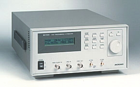
MAT800 High-speed programmable attenuator
Windows95 / 98 / Me / 2000 / XP correspondence GP-IB,
RS-232C and software for making attenuation program are standard accessories.
Optimum for evaluation of communication quality of such wireless
communication equipments as W-CDMA, CDMA, GSM, PDC, PHS, ETC, wireless LAN and
Bluetooth.
MAT800 is a multi-functional and all-out
programmable attenuator that is capable of controlling the attenuation of
microwave signal at an ultra-high speed.
Features
![]() 128kwords built-in program memory
128kwords built-in program memory
![]() Maximum 2µs switching (readout) speed
Maximum 2µs switching (readout) speed
![]() Three readout modes of FREE, BURST and GATE
Three readout modes of FREE, BURST and GATE
![]() Setup of hold off period by the number of clocks or by time
Setup of hold off period by the number of clocks or by time
2. The software for making attenuation program is a standard accessory
3. GP-IB and RS-232C are equipped as standard
accessories
4. Four models are prepared for every frequency band
![]() model A : 1.5 to 4.5GHz
model A : 1.5 to 4.5GHz
![]() model B : 3.0 to 9.0GHz
model B : 3.0 to 9.0GHz
![]() model C : 4.5 to 13.5GHz
model C : 4.5 to 13.5GHz
![]() model D : 1.95 to 5.85GHz
model D : 1.95 to 5.85GHz
5. The maximum attenuation is 80dB
6. The minimum step size of attenuation is 0.05dB
| 1. Attenuation mode | 2. Attenuation |
|
Select either manual
setup or programmed setup. |
Set the attenuation. It is valid in the manual mode. 0 to 80 dB in 0.05 dB steps. |
| 3. Filter | 4. Readout clock |
|
Select switching
response time of attenuator. |
Set readout clock of program memory. External clock and manual clock are available. |
| 5. Program length | 6. Program hold off period |
|
Set program memory length. 8 to 131,072 words in one word step. |
Set hold off period of
program memory, that is, the time till the next readout is started.
Perform setup by number of readout clocks or by time. |
| 7. Readout mode | 8. Setup |
|
Set readout method of program memory from Free, Burst and Gate. * Refer to "Program readout mode". |
Set parameters of RS-232C or GP-IB. |
| 9. External readout clock | 10. Trigger input |
|
Connector for input of external clock for reading program memory. |
Connector for input of
trigger signal for such read mode as Burst or Gate. |
| 11. SYNC output | 12. Attenuator input / output |
|
A signal synchronized
with the top address of the program memory is output. |
SMA connector for attenuator input / output. |
Setting of attenuation
|
Two methods are available for setup of attenuation ; manual or program. Select one by "ATTEN MODE".
|
The method of a program
|
When it is necessary to use the program mode, input the program
(waveform) on a Windows computer using "Software for making
attenuation program", which is provided as a standard accessory.
Then transfer this attenuation data to the memory of MAT800 using
RS-232C or GP-IB. Readout clock, program length, hold off period,
readout mode and filter are set from the computer. Of course it is
possible to set by keys on the front panel. Connect external clock and
trigger signal as required. 1. Standard waveforms input The nine types of standard waveforms are prepared. They are sine wave, triangle wave, square wave, ramp wave, sinX / X, (1-ε-ax), ε-ax white noise and DC.
2. Straight line input
Two specified points are linked together by means of
a straight line.
3.
Arithmetic calculation input
|
Program readout mode
|
Three program readout modes are
available ; Free, Burst and Gate. Readout is executed regardless of the
trigger signal in the Free mode. In the Burst mode, the readout of
program memory is started at the rising edge of the trigger signal, the
attenuation data of the terminating address is held until the next
activation. Therefore, setup of the hold off period is not permitted in
the Burst mode.
|
Application - wireless communication quality test
by changing transmission power
|
|
Specification
| model A | model B | model C | model D | |
| Frequency range | 1.5 to 4.5GHz | 3.0 to 9.0 GHz | 4.5 to 13.5GHz | 1.95 to 5.85GHz |
| VSWR |
< 1.5 @ 2 to 4GHz |
< 1.7
@ 4 to 8GHz |
< 1.8 @ 6 to 12GHz |
< 1.6
@ 2.6 to 5.2GHz |
|
Insertion
loss |
< 2.3dB @ 2 to 4GHz |
<
3.0dB @ 4 to 8GHz |
< 3.5dB @ 6 to 12GHz |
<
2.6dB @ 2.6 to 5.2GHz |
| Attenuator | |
| Setting range | 0 to 80dB |
| Setting resolution | less than 0.05dB |
| Accuracy | less than ±0.5dB @ 0 to 10dB |
| (at center of frequency range and +10dBm input) | less than ±0.8dB @ >10 to 30dB |
| less than ±1.0dB @ >30 to 50dB | |
| less than ±1.5dB @ >50 to 64dB | |
| less than ±2.0dB @ >64 to 74dB | |
| less than ±3.0dB @ >74 to 80dB | |
| Impedance | 50ohm nominal |
| Filter | 1µs to 3ms, 1-3 step |
| Maximum input level | 100mW @ CW or peak power |
| Input damage level | 0.8W @ average power |
| 20W @ peak power of 1µs pulse | |
| Input / output connector | SMA |
| Readout clock input | |
| Input level | TTL level |
| Maximum frequency | 500kHz |
| Input impedance | 10kohm ±5% |
| Minimum pulse width | more than 200ns (both of high and low) |
| Input damage level | ±20V (DC + ACpeak) max |
| Connector | BNC |
| Trigger input | |
| Input level | TTL level |
| Input impedance | 10kohm ±5% |
| Minimum pulse width | more than 1µs |
| Input damage level | ±20V (DC + ACpeak) max |
| Connector | BNC |
| SYNC output | |
| Output level | TTL level |
| Rise / Fall time | less than 100ns |
| Output impedance | approx. 100ohm |
| Connector | BNC |
| Functions | |
| Attenuation mode | Manual and Program |
| Program mode | |
| Program length | 8 to 131072words, (available for setting in one word step) |
| Readout clock | |
| Internal clock | 100Hz to 500kHz, 1-2-5 step |
| External clock | DC to 500kHz |
| Manual clock | Due to pressing ENTER key |
| Hold off period | |
| Clock setting | 0 to 65535 clocks of readout clock (available for each clock) |
| 0 to 6.5535sec (by 100µs step) | |
| Time setting | Free, Burst, Gate |
| Read mode | |
| Backup of program | Program data is automatically saved when turning off. |
| Software for making attenuation program | |
| Effective OS | Windows95 / 98 / / Me /2000 / XP |
| Making waveform | |
| Standard waveform | |
| Waveform type | Sine, Triangle, Square, Ramp, sinX / X, (1-ε-ax), ε-ax, White noise and DC |
| Parameter |
Data size, Attenuation (except DC), Offset, |
| Cycle (except White noise and DC), Phase (°) | |
| (except White noise and DC), Duty ratio (%) | |
| (only Square wave), Zero cross (only sinX / X), | |
| Attenuation ratio ( (1-ε-ax) and ε-ax) | |
| Straight line | Link two points with line |
| Calculation | +, -, ×, Clipping, Absolute, Mirror, Smoothing, Resize, Offset |
| One point input | Input each point |
| Editing of waveform | Cut, Copy, Paste, Undo, Delete |
| File |
New, Open, Close, Save, Save as, Data import, |
Products list | brand | Model No. | Home