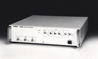
MC125A/MC125B Time Interval Analyzer
Continuous measurement of time intervals and pulse widths a resolution of 125ps (8GHz clock)
Ultarlow-cost pulse width analyzer now available from MICRONIX
<Designed solely for time measurement, with data display and analysis by the host>
The MC125A / B pulse width analyzer can measure momentary values of superhigh-speed time (125ps resolution) for the overall evaluation of signal time. These units have been developed as a low-cost version of the well-received MC1250 by taking over its time measurement function only, with data display and analysis performed by a host such as a personal computer. Furthermore, since these units allow high-speed data transfer, they can also be used in production lines, rather than simply for research and development purposes.
![]() Minimum measurement cycle : 70ns <MC125A>, 225ns <MC125B>
Minimum measurement cycle : 70ns <MC125A>, 225ns <MC125B>
![]() Memory capacity : 128KW <MC125A>, 32KW <MC125B>
Memory capacity : 128KW <MC125A>, 32KW <MC125B>
![]() Reference crystal : Sealed into an oven, supers table <MC125A>, regular
highs table <MC125B>
Reference crystal : Sealed into an oven, supers table <MC125A>, regular
highs table <MC125B>
Main features
| (1) |
A
superhigh-speed sampling clock of 8GHz |
| (2) |
Capable
of measuring momentary signal values without interruption |
 |
| (3) |
Data
display and analysis performed by a host |
| (4) |
High-speed
data transfer through parallel outputs |
| (5) |
Two
output mode |
| (6) |
32-bit
counter |
| (7) |
Large-capacity
memory of 128Kwords |
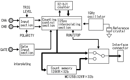
Operating principle
The diagram shown below is a block diagram of the pulse width analyzer. The 125ps resolution is obtained by dividing the 1GHz clock into eight phases. The output data can be either real-time data or data stored in the memory.
|
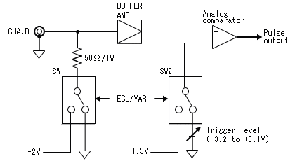
The diagram below shows the pulse width analyzer 's channel A / B input circuit. If ECL is selected as the trigger level, the input 's 50ohm resistor is tied to -2V, and the trigger level is set to -1.3V. Conversely, if VAR is selected, the 50ohm resistor is tied to GND, and the trigger level in this case can be set to anywhere between -3.2V and +3.2V.
|
Capturing the desired data
Date-capturing function
![]() RUN / STOP
RUN / STOP
This function allows you to start or stop measurement. Measurement can be started (restarted) and stopped (paused) any number of times until the memory becomes full.
![]() MEASURING lamp
MEASURING lamp
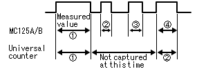
This lamp remains lit while the input signal is being measured. In other words, this lamp will be lit if the pulse width analyzer is in the RUN state and the gate input is active and CHA or CHB is normally input.
![]() Gate function
Gate function
Measurement is enabled when the gate input is pulled low.
| Example of gate
function (A•B interval : from the rise of CHA to the fall of CHB) 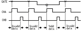 |
Various time measurements are possible
Time measurements items
![]() A•B interval measurement
A•B interval measurement
The time from the rising (or falling) edge of the signal applied to CHA to the rising (or falling) edge of the signal applies to CHB is measured.
| Example of
A•B interval measurement (From the rise of CHA to the fall of CHB) 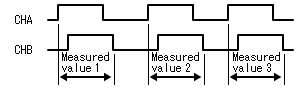 |
![]() Pulse width measurement
Pulse width measurement
The positive or negative pulse width or the signal applied to CHA is measured.
Example of
positive pulse width measurement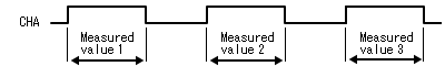 |
Data display and analysis performed by the host
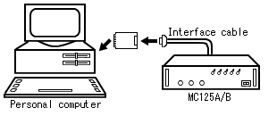
![]() System configuration
System configuration
The diagram below shows a typical system configuration using a personal computer as the host. Connect the pulse width analyzer and the personal computer using the interface cable that is attached to your pulse width analyzer as a standard accessory. Install a conventional PIO (parallel input / output) board, which is readily available on the market, in the slot of the personal computer.
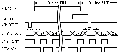
![]() Two output
modes for expanded application
Two output
modes for expanded application
When
the pulse width analyzer is in the RUN and STOP modes, the output data is as
follows :
[During RUN]
The measured data is stored in the memory while, at the same time, being output
directly to the interface connector real-time mode. If the measurement time per
data is longer than the time required for the data to be taken in by the
personal computer, it is possible to transfer data to the personal computer.
Furthermore, by adding a simple external circuit to the pulse width analyzer, it
is possible to determine limits with respect to the upper / lower limit values (judgement
of GO or NO GO), irrespective of the memory capacity, or output the voltage
level (i.e., deviation output) which is proportional to a difference from the
reference value, thus enabling data to be monitored for many hours.
[During STOP]
The data stored in the memory during RUN is output to the interface connector
memory mode. By using the data captured on the host side, it is possible to
perform various analyses, including a histogram analysis and a time variation
analysis.
|
The data transfer procedures used during RUN and STOP are exactly the same.
Applications
![]() Evaluation of pit widths in magnet-optical and optical disks
Evaluation of pit widths in magnet-optical and optical disks
![]() Measurement of the wow / flutter and startup
characteristics of precision motors
Measurement of the wow / flutter and startup
characteristics of precision motors
![]() Measurement of pulse-to-pulse skews, and
measurement of timing
Measurement of pulse-to-pulse skews, and
measurement of timing
![]() Measurement of jitters in pulse widths and cycles,
and modulation analysis
Measurement of jitters in pulse widths and cycles,
and modulation analysis
Specification
| Input section | |||||||||||||||||||||||||||||||||||||||||||||||||||||||||||||||||||||||||||||||||||||||||||||||||||||||||
| Input channels | CHA and CHB | ||||||||||||||||||||||||||||||||||||||||||||||||||||||||||||||||||||||||||||||||||||||||||||||||||||||||
| Input impedance | 50ohm ±1ohm | ||||||||||||||||||||||||||||||||||||||||||||||||||||||||||||||||||||||||||||||||||||||||||||||||||||||||
| Attenuator | × 1 / 1 | ||||||||||||||||||||||||||||||||||||||||||||||||||||||||||||||||||||||||||||||||||||||||||||||||||||||||
| Frequency bandwidth | DC to 250MHz | ||||||||||||||||||||||||||||||||||||||||||||||||||||||||||||||||||||||||||||||||||||||||||||||||||||||||
| Sensitivity | more than 200mVp-p | ||||||||||||||||||||||||||||||||||||||||||||||||||||||||||||||||||||||||||||||||||||||||||||||||||||||||
| Trigger level | ECL and VAL (CHA and CHB are set commonly) | ||||||||||||||||||||||||||||||||||||||||||||||||||||||||||||||||||||||||||||||||||||||||||||||||||||||||
| VAL range | -3.2 to +3.2V, at 100mV step | ||||||||||||||||||||||||||||||||||||||||||||||||||||||||||||||||||||||||||||||||||||||||||||||||||||||||
| Trigger slope | Rise and Fall | ||||||||||||||||||||||||||||||||||||||||||||||||||||||||||||||||||||||||||||||||||||||||||||||||||||||||
| Input damage level | ±40V (DC + ACpeak) max or 1 watt | ||||||||||||||||||||||||||||||||||||||||||||||||||||||||||||||||||||||||||||||||||||||||||||||||||||||||
| Gate input section | |||||||||||||||||||||||||||||||||||||||||||||||||||||||||||||||||||||||||||||||||||||||||||||||||||||||||
| Input impedance | 100kohm ±2% | ||||||||||||||||||||||||||||||||||||||||||||||||||||||||||||||||||||||||||||||||||||||||||||||||||||||||
| Trigger level | TTL level | ||||||||||||||||||||||||||||||||||||||||||||||||||||||||||||||||||||||||||||||||||||||||||||||||||||||||
| Operation | Active low (measured at low level) | ||||||||||||||||||||||||||||||||||||||||||||||||||||||||||||||||||||||||||||||||||||||||||||||||||||||||
| Input damage level | ±50V (DC + ACpeak) max | ||||||||||||||||||||||||||||||||||||||||||||||||||||||||||||||||||||||||||||||||||||||||||||||||||||||||
| Counter section | |||||||||||||||||||||||||||||||||||||||||||||||||||||||||||||||||||||||||||||||||||||||||||||||||||||||||
| Time resolution | 125ps (fix) | ||||||||||||||||||||||||||||||||||||||||||||||||||||||||||||||||||||||||||||||||||||||||||||||||||||||||
| Measuring range | 25ns to 250ms | ||||||||||||||||||||||||||||||||||||||||||||||||||||||||||||||||||||||||||||||||||||||||||||||||||||||||
| Accuracy | ±50ps (trigger error) ±50ps (time-base error) ±125ps (±1 count error) | ||||||||||||||||||||||||||||||||||||||||||||||||||||||||||||||||||||||||||||||||||||||||||||||||||||||||
| Min. measuring period | more than 70ns <MC125A> / more than 225ns <MC125B> | ||||||||||||||||||||||||||||||||||||||||||||||||||||||||||||||||||||||||||||||||||||||||||||||||||||||||
| Counter memory section | |||||||||||||||||||||||||||||||||||||||||||||||||||||||||||||||||||||||||||||||||||||||||||||||||||||||||
| Memory size | 128Kwords × 32bits <MC125A> / 32Kwords × 32bits <MC125B> | ||||||||||||||||||||||||||||||||||||||||||||||||||||||||||||||||||||||||||||||||||||||||||||||||||||||||
| Data format | Counted data 31bits, over flow 1bits | ||||||||||||||||||||||||||||||||||||||||||||||||||||||||||||||||||||||||||||||||||||||||||||||||||||||||
| Reference frequency | |||||||||||||||||||||||||||||||||||||||||||||||||||||||||||||||||||||||||||||||||||||||||||||||||||||||||
| Frequency | 10MHz | ||||||||||||||||||||||||||||||||||||||||||||||||||||||||||||||||||||||||||||||||||||||||||||||||||||||||
| Aging rate |
less than ±1 × 10⁻⁹ / day,
less than ±3 × 10⁻⁸ / year <MC125A> |
||||||||||||||||||||||||||||||||||||||||||||||||||||||||||||||||||||||||||||||||||||||||||||||||||||||||
| Short term stability | 1 × 10⁻¹⁰, 1second average <MC125A> | ||||||||||||||||||||||||||||||||||||||||||||||||||||||||||||||||||||||||||||||||||||||||||||||||||||||||
| Temperature stability | less than ±3 × 10⁻⁸ <MC125A> / less than ±1 × 10⁻⁶ (23 ±10°C) <MC125B> | ||||||||||||||||||||||||||||||||||||||||||||||||||||||||||||||||||||||||||||||||||||||||||||||||||||||||
| Capture data | |||||||||||||||||||||||||||||||||||||||||||||||||||||||||||||||||||||||||||||||||||||||||||||||||||||||||
| Control | RUN / STOP, gate function | ||||||||||||||||||||||||||||||||||||||||||||||||||||||||||||||||||||||||||||||||||||||||||||||||||||||||
| Measuring item | |||||||||||||||||||||||||||||||||||||||||||||||||||||||||||||||||||||||||||||||||||||||||||||||||||||||||
| A•B interval measurement | Measurement of time from CHA to CHB | ||||||||||||||||||||||||||||||||||||||||||||||||||||||||||||||||||||||||||||||||||||||||||||||||||||||||
| Pulse width measurement | Measurement of positive pulse width of CHA (from rising to falling edge of CHA) or negative pulse width (from falling to rising edge of CHA) | ||||||||||||||||||||||||||||||||||||||||||||||||||||||||||||||||||||||||||||||||||||||||||||||||||||||||
| Interface | |||||||||||||||||||||||||||||||||||||||||||||||||||||||||||||||||||||||||||||||||||||||||||||||||||||||||
| Transfer method | Parallel output | ||||||||||||||||||||||||||||||||||||||||||||||||||||||||||||||||||||||||||||||||||||||||||||||||||||||||
| Transfer speed | At RUN (measuring time)+ | ||||||||||||||||||||||||||||||||||||||||||||||||||||||||||||||||||||||||||||||||||||||||||||||||||||||||
| 45ns <MC125A> | |||||||||||||||||||||||||||||||||||||||||||||||||||||||||||||||||||||||||||||||||||||||||||||||||||||||||
| 200ns <MC125B> | |||||||||||||||||||||||||||||||||||||||||||||||||||||||||||||||||||||||||||||||||||||||||||||||||||||||||
| max. 70ns <MC125A> | |||||||||||||||||||||||||||||||||||||||||||||||||||||||||||||||||||||||||||||||||||||||||||||||||||||||||
| 225ns <MC125B> | |||||||||||||||||||||||||||||||||||||||||||||||||||||||||||||||||||||||||||||||||||||||||||||||||||||||||
| At STOP max. 300ns | |||||||||||||||||||||||||||||||||||||||||||||||||||||||||||||||||||||||||||||||||||||||||||||||||||||||||
| Output data | At RUN output counted data directly | ||||||||||||||||||||||||||||||||||||||||||||||||||||||||||||||||||||||||||||||||||||||||||||||||||||||||
| At STOP output counted data stored in memory | |||||||||||||||||||||||||||||||||||||||||||||||||||||||||||||||||||||||||||||||||||||||||||||||||||||||||
| Condition | TTL level | ||||||||||||||||||||||||||||||||||||||||||||||||||||||||||||||||||||||||||||||||||||||||||||||||||||||||
|
Connector pin assignment
|
|||||||||||||||||||||||||||||||||||||||||||||||||||||||||||||||||||||||||||||||||||||||||||||||||||||||||
| General | |||||||||||||||||||||||||||||||||||||||||||||||||||||||||||||||||||||||||||||||||||||||||||||||||||||||||
| Operating temperature | 0 to 40°C (Guaranteed at 23 ±10°C) | ||||||||||||||||||||||||||||||||||||||||||||||||||||||||||||||||||||||||||||||||||||||||||||||||||||||||
| Operating humidity | less than 40°C / 90% RH (Guaranteed at less than 33°C / 80% RH) | ||||||||||||||||||||||||||||||||||||||||||||||||||||||||||||||||||||||||||||||||||||||||||||||||||||||||
| Storage temperature | -10 to 60°C, less than 60°C / 80% RH | ||||||||||||||||||||||||||||||||||||||||||||||||||||||||||||||||||||||||||||||||||||||||||||||||||||||||
| Power supply | 85 to 132V / 170 to 264V AC (switched inside) | ||||||||||||||||||||||||||||||||||||||||||||||||||||||||||||||||||||||||||||||||||||||||||||||||||||||||
| Power consumption | approx. 116VA | ||||||||||||||||||||||||||||||||||||||||||||||||||||||||||||||||||||||||||||||||||||||||||||||||||||||||
| Dimensions | 430 (W) × 99 (H) × 440 (D) | ||||||||||||||||||||||||||||||||||||||||||||||||||||||||||||||||||||||||||||||||||||||||||||||||||||||||
| Weight | approx 15.8kg | ||||||||||||||||||||||||||||||||||||||||||||||||||||||||||||||||||||||||||||||||||||||||||||||||||||||||
| Accessories | |||||||||||||||||||||||||||||||||||||||||||||||||||||||||||||||||||||||||||||||||||||||||||||||||||||||||
| Power cable | (1pc) | ||||||||||||||||||||||||||||||||||||||||||||||||||||||||||||||||||||||||||||||||||||||||||||||||||||||||
| Fuse | (1pc) | ||||||||||||||||||||||||||||||||||||||||||||||||||||||||||||||||||||||||||||||||||||||||||||||||||||||||
| Interface cable | (1pc) | ||||||||||||||||||||||||||||||||||||||||||||||||||||||||||||||||||||||||||||||||||||||||||||||||||||||||
| Instruction manual | (1pc) | ||||||||||||||||||||||||||||||||||||||||||||||||||||||||||||||||||||||||||||||||||||||||||||||||||||||||
| Options | |||||||||||||||||||||||||||||||||||||||||||||||||||||||||||||||||||||||||||||||||||||||||||||||||||||||||
|
|
|||||||||||||||||||||||||||||||||||||||||||||||||||||||||||||||||||||||||||||||||||||||||||||||||||||||||
|
Transmission of measured data and analysis shown in below are performed. [Analysis item] Histogram analysis, Time variation analysis, Measured values display and Statistics (maximum, minimum, average and 3Sigma) |
|||||||||||||||||||||||||||||||||||||||||||||||||||||||||||||||||||||||||||||||||||||||||||||||||||||||||
|
|
|||||||||||||||||||||||||||||||||||||||||||||||||||||||||||||||||||||||||||||||||||||||||||||||||||||||||
|
|
|||||||||||||||||||||||||||||||||||||||||||||||||||||||||||||||||||||||||||||||||||||||||||||||||||||||||
|
|
|||||||||||||||||||||||||||||||||||||||||||||||||||||||||||||||||||||||||||||||||||||||||||||||||||||||||
|
|
|||||||||||||||||||||||||||||||||||||||||||||||||||||||||||||||||||||||||||||||||||||||||||||||||||||||||
|
|
|||||||||||||||||||||||||||||||||||||||||||||||||||||||||||||||||||||||||||||||||||||||||||||||||||||||||
Products list | brand | Model No. | Home