INTRODUCTION TO HDMI
Developed by Sony, Hitachi, Thomson (RCA), Philips, Matsushita (Panasonic), Toshiba, and Silicon Image, the
High-Definition Multimedia Interface (HDMI) has emerged as the connection standard for HDTV and the
consumer electronics market. HDMI is the first and only digital interface to combine uncompressed high-definition
video, multi-channel audio and intelligent format and command data in a single digital interface. For end-users,
use of a single cable for audio and video dramatically simplifies home theater system installation by eliminating
the tangle of cables typically associated with home theater system components.
Most importantly, HDMI offers significant advantages over analog A/V connections, including the ability to transmit
uncompressed digital video and audio content. And INTEL allows use of its proprietary High Definition Content
Protection (HDCP) scheme for DVI and HDMI, perhaps the best solution for the digital video interface, which
transfers high definition video content and is easy to implement.
Since the Digital Display Working Group (DDWG), the standards body that specifies DVI, decided to focus on the
computing market, the HDMI working group has taken over the role in consumer electronics. In addition to
numerous device and display manufacturers, Hollywood studios and cable and satellite operators also support
HDMI.
Key Specifications and Product Features
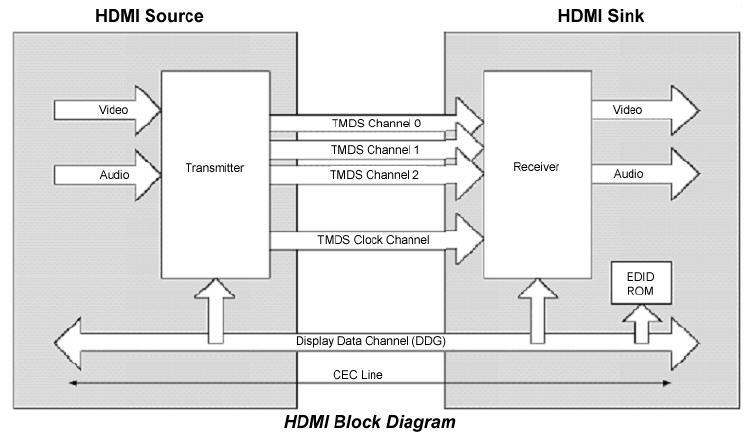
HDMI system architecture is defined as consisting of Sources, Sinks, Repeaters, and Cable Assemblies. A given
device may have one or more HDMI inputs, and one or more HDMI outputs.
Each HDMI input on a device follows all of the rules for an HDMI Sink, and each HDMI output follows all of the
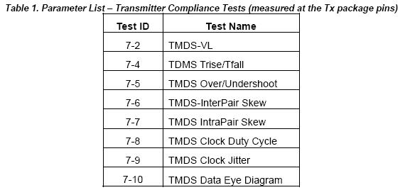
rules for an HDMI Source. Consequently, each HDMI input is fully tested for compliance using the tests specified
for Sink devices, and each HDMI output is fully tested against the full set of tests specified for Source devices.Required Test Equipment Capabilities
• The Jitter/Eye Analyzer must be capable of accurately indicating the amount of jitter, or the actual eye
diagram, on the tested transition minimized differential signal (TMDS).
• The transfer function for an ideal recovery clock is given by Equation 4-1 from HDMI Specification 1.0a
and 1.2a, shown below. An ideal clock recovery unit (CRU) would perfectly match this function.
• Across the tested clock frequency range, the Jitter/Eye Analyzer’s CRU shall have a jitter transfer
amplitude that differs from the ideal transfer function by no more than ±0.2 dB from DC to10 MHz. At
20 MHz the difference must be less than ±1 dB, and at 50 MHz, less than +2/-6 dB. From DC to 20 MHz,
the jitter transfer phase response must be within ±1.8 degrees of the phase response of the ideal
recovery clock.
H(jω) = 1/(1 + jω/ω0)
where ω0 = 2πf0, f0 = 4.0 MHzINTRODUCTION TO SDA-HDMI
The LeCroy HDMI Compliance Test Software for the SDA4000A, SDA4020A, SDA5000A, SDA6000A, SDA6020
and SDA11000 serial data analyzers is designed with the following major objective in mind:
SDA-HDMI provides the necessary tools to develop HDMI compliant source devices in a systematic, stepby-
step fashion, in accordance with the latest standards and specification documents published by HDMI
founders.
The standard features of the SDA also provide a broad tool set for advanced debugging of these interfaces,
including jitter, eye pattern, and bit error rate.
The LeCroy HDMI Compliance Software (SDA-HDMI) can work with version 4.6.3 or later of X-Stream DSO
firmware.
Required Equipment
• SDA 4000A, SDA 4020A, SDA 5000A, SDA 6000A, SDA 6020 or SDA 11000
(16 Mpts memory per channel)
• HDMI Compliance Test software option (LeCroy SDA-HDMI)
• 2 differential probes (D350 type)
• 1 set of compliance test fixtures (TF-HDMI: TPA-P-DI and TPA-P-SE)
• A host computer, though not required, is highly recommended to execute X-Replay, the compliance &
development software engine.
• 3.3 V power supply
• EDID interface or means to control the interface
HDMI Compliance Test Fixtures
The HDMI standard describes a set of two fixtures that are used to connect to the signal under test. The fixtures
are known as the TPA-P-DI and the TPA-P-SE. The TPA-P-DI is used to test the signal as a differential input, and
the TPA-P-SE is used to test the signal as a single-ended input. TPA-P-DI and TPA-P-SE are available from
LeCroy as a set, under product code TF-HDMI.
Both fixtures terminate all differential lines with a 50 ohm resister to Vcc (3.3 V) on board, and provide probing
points for an active probe to pick up the signal.
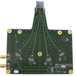
Figure 1. HDMI test fixture TF-HDMI TPA-P-DI provides an HDMI plug connector to connect an HDMI source device.
The 3.3 V power supply connection is at the square pin header. All TMDS differential signals, D0, D1, D2, and CLK are
picked up from corresponding square pin headers. The EDID emulator is connected to an 8-pin square pin header to
communicate with the source device under the test..
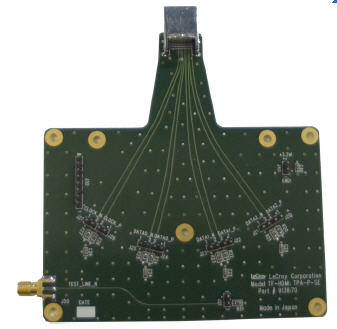
Figure 2. HDMI test fixture TF-HDMI TPA-P-SE is similar to TPA-P-DI but TMDS differential lines are separated as two
single-ended lines for the corresponding test.
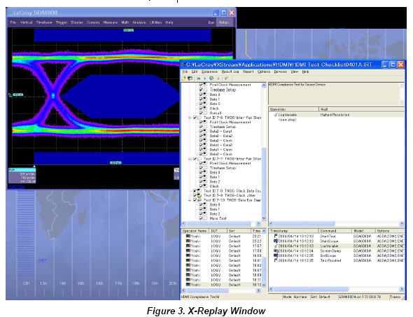
What Is X-Replay?
The HDMI Compliance Test software application incorporates X-Replay, a unique application framework.
X-Replay is an MS Windows-based application that contains all the commands and instructions necessary to
configure, acquire, display, and report measurement results. For instance, the X-Replay environment enables you
to:
• Create or change test criteria in order to make context-sensitive parametric measurements.
• Export all test results as XML for import into a database program, such as Microsoft Access, for further
manipulation.
• Generate reports from within X-Replay, showing the latest test results. Reports are html and are meant to
be viewed with Microsoft Internet Explorer.
The HDMI Compliance Test software resides in X-Stream DSO software in the scope, and it is activated through
the use of an alphanumeric code matched to the scope’s serial number. Unique to each scope serial number, this
code is activated when you order SDA-HDMI software.
While the software key enables the scope to perform the measurements, X-Replay contains the HDMI script, the
test results database, and the report generation engine. For ultimate flexibility, X-Replay can be executed from a
host computer at a remote location, provided that there is a Windows-compatible network connection.SOFTWARE INSTALLATION AND SYSTEM CONFIGURATION
Option Key Installation
When ordered as an option for a new instrument, no installation of SDA-HDMI is necessary. Installation is
required, however, when the option is ordered after the oscilloscope is purchased. An option key will be issued at
the time the option is purchased.
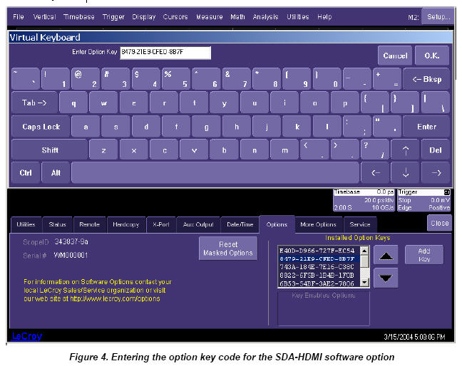
To enter the option key code,
1. Touch Utilities in the menu bar, then Utilities Setup… in the drop-down menu.
2. Select the “Options” tab from the utilities dialog.
3. In the Options dialog, touch the Add Key button and enter the option key in the dialog box, using the onscreen
keyboard.
CD-ROM Installation
When ordered as an upgrade to an existing X-Stream instrument, an Application Software CD-ROM is supplied
containing X-Replay and other software installation files. Follow the specific instructions in the Installer
application. When necessary, the installation process will prompt you for storage locations for data files and test
results, reports, scripts, etc.PREPARING TO MAKE HDMI MEASUREMENTS
Channel Deskew (SMA Cables)
HDMI signals are properly probed using two separate channels on the oscilloscope connected to the appropriate
SMA jacks on the test fixture. The highest measurement accuracy is achieved when the timing skew between the
two channels is calibrated. This is performed using the “Deskew” control on one of the two channels to which the
differential signal is connected, as follows:
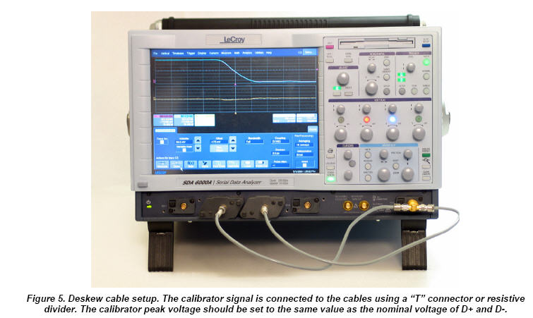
1. Attach the calibrator signal to both input channels using a “T” connector to rout the calibrator signal on the
SDA front panel through the same cables that will be connected to the fixture.
2. Set interpolation of both channels to Sinx/x, using the “Interpolation” control in the “Vertical Adjust” dialog
for each channel.
3. Create a Difference math waveform by selecting Math in the menu bar, then Math Setup… in the dropdown
menu. Enter the channels to which your signal is connected in the Source1 and Source2 fields,
and select Difference from the Operator1 menu. The math function is thus defined as the difference
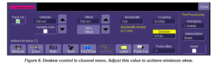
between the 2 channels probing the D+ and D- signals.4. While viewing the math trace, adjust the Deskew control in one of the channels until the math trace is as
flat as possible.
Note: With the “Deskew” control highlighted, you can use the front panel ADJUST knob to make the adjustment.
The best accuracy is achieved by setting the level of the calibrator signal to match the expected levels of the
signal under test, and with the calibrator set to its maximum frequency (5 MHz). The calibrator settings can be
found in the “Utilities” dialog under the Aux Output tab.
Save the deskew value for Channel 2 for use later in the test program