|
||
|
||
|
||
|
From
power electronics such as inverters and wireless charging to
servo control, evaluation of electronic components and batteries,
and even advanced bioresearch
Loop Characteristics Servo CharacteristicsTransfer CharacteristicsImpedanceAdmittancePSRRPLL Response CharacteristicsVibration Transfer CharacteristicsElectrochemical Impedance
|
Our FRAs are suitable to measure frequency response for many industries from
electronic circuits, electronic components, and materials to mechatronics and
electrochemical applications. Equipped with the performance and functionality
to support many industries, our FRAs provide highly
reproducible measurement data and more efficient testing operations. |
|
|
Measurement Frequency : 10 µHz to 15 MHz |
|
Measurement Speed : 0.5 ms/point |
|
Basic Accuracy : Gain: ±0.01dB, Phase: ±0.06° |
|
Maximum Measurement Voltage : 600 Vrms |
|
Maximum Input Voltage : 600 V CATⅡ/300 V CATⅢ |
|
Isolation : 600 V CATⅡ/300 V CATⅢ |
|
Dynamic Range : 140 dB |
Functions to ensure reliable and highly accurate measurements |
||||
• |
Auto Ranging |
• |
Automatic High Density Sweep |
|
• |
Amplitude Compression Function |
• |
Integrator |
|
• |
Automatic Integrator |
• |
Delay Function |
|
• |
Differential and integral operations |
• |
Sequence Measurement Function |
|
• |
Marker Search Function |
• |
Group Delay |
|
• |
Measurement Function for Changing the Frequency at 0° -phase |
|||
• |
Impedance Measurement: |
|||
|
||||
|
Measurement of resonance characteristics of piezo element |
|||
|
Measurement of characteristics of multi-layer ceramic capacitor to which voltage is applied |
|||
|
Measurement of internal impedance of battery cell |
|||
|
||||
|
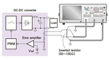
Loop gain measurement of DC-DC converter |
|||
By measuring the loop gain characteristic of the DC - DC converter under the actual voltage applied to, We quantitatively evaluate circuit stability from phase margin and gain margin. |
|
|
Conditions |
Load: DC-DC converter
with switching frequency 1MHz |
|
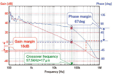
Results |
||
• |
Phase margin, gain margin. |
||
The larger the margin, the more ringing and oscillation can be suppressed. |
|||
• |
Crossover frequency |
||
It is a guide of responsiveness at load fluctuation. |
|||
|
With marker search function, phase margin and gain margin can be detected automatically. |
<="" div="" wfd-id="12" style="margin: 20px auto 10px; border-width: 1px 0px 0px; border-top-style: dotted; border-top-color: rgb(51, 51, 51); border-right-style: initial; border-right-color: initial; border-bottom-style: initial; border-bottom-color: initial; border-left-style: initial; border-left-color: initial;"> |
||||
Other Example |
||||
|
Measurement of Transmission Efficiency on Wireless charging |
|||
|
Measurement of Mechanical Servo Characteristic |
|||
|
Measurement of Frequency Response of Filters and Amplifiers |
|||
|
Acoustic Analysis |
|||
|
Vibration Analysis |
|||